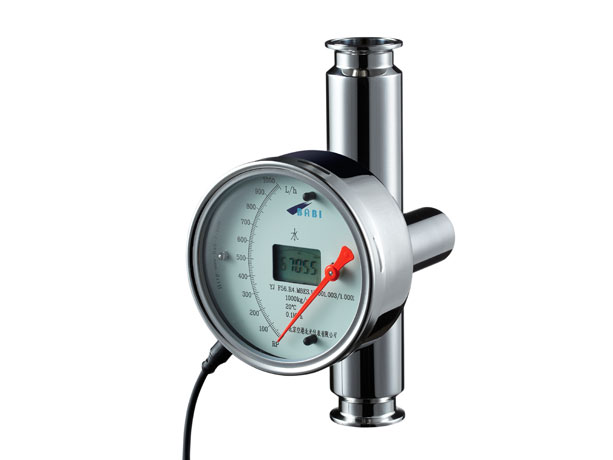

Features
◆ Designed for food industry.
◆ Easy to disassemble, clean and maintain.
◆ Housing made of stainless steel, corrosion resistant.
◆ Indicator made of stainless steel by stamping forming, surface polished, beautiful and compact structure.
◆ Local display indicator and local display with transmitter indicator are optional to meet a variety of control requirements.
◆ Varieties of nominal diameter are available up to DIN3276(I SO2852, ASME and so on).
◆ Standard clamp connection.
■ Current output specification
Power supper: (12 to 36) VDC
Rated voltage: 24VDC
Output signal: (4 to 20) mA/HART protocol remote signal.
Type
F56(Food Industrial Level)
Fluid type
Liquid, gas, steam
Flow range(Convert to standard medium, 100% values)
Water:20℃
(10 to 100000) L/h,Special order according to user requirements
Air:0.1013MPa,20℃
(0.7 to 3000)Nm3/h,Special order according to user requirements
Rangeability
10:1
Indication accuracy
Local type
Mechanical pointer indication
1.5,2.5,4.0(F.S. as standart)
Digital display (battery powered, service life 1 years)
1.5,2.5,4.0(F.S. as standart)
Transmitter: simultaneous pointer indication and digital display
1.5,2.5,4.0(F.S. as standart)
Fluid temperature
Local type
Mechanical pointer indication
‐80℃ to +200℃(PTFE:0 to 80℃)
Digital display (battery powered, service life 1 years)
‐40℃ to +120℃(PTFE:0 to 80℃) High temperature type 200℃
Transmitter: simultaneous pointer indication and digital display
‐40℃ to +120℃(PTFE:0 to 80℃) High temperature type 200℃
Ambient temperature
Local type
Mechanical pointer indication
‐40℃ to +120℃
Digital display (battery powered, service life 1 years)
‐20℃ to +60℃
Transmitter: simultaneous pointer indication and digital display
‐20℃ to +60℃
Fluid viscosity
DN15:10 to 25(l/h) η<1 mPa.s, >25(l/h) η<5 mPa.s; DN25:η<20 mPa.s; DN50 to 250:η<30 mPa.s
Fluid pressure
DN15~DN50
4.0MPa
DN80~DN250
1.6MPa
Process connection
Sanitary clamp (standard: DIN32676; ISO2852); sanitary union(standard: DIN11851; SMS1145)
Electrical connection
M12 electrical connector
Installation(Flow direction)
Vertical flow direction (bottom→top,top→bottom); Horizontal flow direction (lift→right,right→lift)
Installation conditions
Inlet section ≥ 5 × DN, outlet section ≥ 3 × DN
Protection category
IP65(Other orders need to be explained separately)
Ex‐mark
Ex ia II C T4 to T6 Ga
Ex d II C T6 Gb
Intrinsically safe data
Ui=28V Ii=93mA Pi= 0.65W Ci≤ 5nF Li =0mH
Safe gate data
Uo≤ 28V Io≤ 93mA Po≤ 0.65W Co≥ Ci+Cc Lo≥ Li+Lc
Explosion proof certificate number
CE16.1206X